
Powder Metallurgy Process: The Complete 7-Step Guide [2026]
Complete guide to the powder metallurgy process — from powder production through mixing, compaction, sintering, and post-processing. Covers press-and-sinter PM, MIM, and HIP with real production parameters.
Powder metallurgy (PM) is a family of manufacturing processes that produce metal parts from fine metal powders rather than molten metal. Instead of melting and casting, PM compacts powder into a desired shape and then sinters it at high temperature to fuse the particles into a solid, dense component. The result is a near-net-shape part with excellent dimensional consistency, minimal material waste, and mechanical properties that rival — and sometimes exceed — wrought metals.
At SUMTHIN, we operate a full-scale powder metallurgy and MIM facility producing over 2 million parts per month. Our 20+ years of manufacturing clipper blades via MIM powder metallurgy have given us deep process expertise that extends to any precision metal component. This guide explains every step of the powder metallurgy process in detail — with the real temperatures, pressures, and parameters we use on our production floor.
What Is Powder Metallurgy?
Powder metallurgy encompasses several distinct processes — press-and-sinter (conventional PM), Metal Injection Molding (MIM), Hot Isostatic Pressing (HIP), and additive manufacturing (metal 3D printing). All share the same fundamental principle: start with metal powder, form it into a shape, and consolidate it through heat. The differences lie in how the powder is shaped and the final density achieved.
The global powder metallurgy market is valued at over $30 billion and growing at approximately 7% annually, driven by automotive, medical device, and electronics demand for complex, high-precision parts at lower cost than traditional machining.
Step 1: Metal Powder Production
Everything begins with the powder itself. The characteristics of the starting powder — particle size, shape, distribution, and purity — directly determine the final part's density, strength, and surface finish. The three primary methods for producing metal powder are:
Water Atomization
Molten metal is broken into droplets by high-pressure water jets (80-150 MPa). The rapid cooling produces irregularly shaped particles with good compressibility — ideal for press-and-sinter PM. Typical particle size: 40-150 micrometers. This is the most cost-effective method and accounts for approximately 80% of all PM powder production.
Gas Atomization
Molten metal is atomized by inert gas (argon or nitrogen) at 2-5 MPa. The result is highly spherical powder with excellent flow characteristics — essential for MIM feedstock and metal 3D printing. Typical particle size: 2-20 micrometers for MIM, 15-45 micrometers for additive. Gas-atomized powder costs 2-5x more than water-atomized but delivers superior sintered properties.
Chemical Reduction
Metal oxides are reduced with hydrogen or carbon at elevated temperatures to produce sponge-like powder particles. Common for iron and copper powders. The porous particle structure aids compaction. This method produces the lowest-cost iron powder for high-volume automotive PM parts.
Step 2: Powder Mixing and Blending
Raw metal powder is rarely used alone. It is blended with other powders, lubricants, and sometimes binder systems to create a feedstock optimized for the forming process.
For press-and-sinter PM:
- Base iron powder is mixed with alloying additions (nickel, copper, carbon, molybdenum) to achieve target mechanical properties
- 0.5-1.0% lubricant (zinc stearate, ethylene bis-stearamide) is added to reduce die friction during compaction and extend tool life
- Mixing time: 20-45 minutes in a V-blender or double-cone mixer to achieve homogeneity
- Lot-to-lot consistency is verified by apparent density testing (ASTM B212) and flow rate testing (ASTM B213)
For MIM (Metal Injection Molding):
- Ultra-fine powder (2-20 micrometers) is compounded with a multi-component polymer binder system (polyoxymethylene + wax + polyethylene)
- Metal-to-binder ratio: approximately 60% metal / 40% binder by volume (92-94% metal by weight)
- Compounding is done in a twin-screw extruder at 150-190°C
- The output is pelletized into uniform feedstock granules for injection molding
Step 3: Compaction / Forming
The mixed powder is shaped into a "green part" — a fragile, near-net-shape preform that holds together through mechanical interlocking and binder adhesion. The forming method depends on the PM process:
Die Compaction (Press-and-Sinter)
Powder is loaded into a rigid steel die and compressed by upper and lower punches at 400-800 MPa (60,000-120,000 psi). Cycle time: 5-15 seconds per part. The green part has approximately 80-90% theoretical density. Complex multi-level parts require multi-action presses with independent punch movements.
Injection Molding (MIM)
Feedstock pellets are heated to 160-190°C and injected into a precision steel mold at 50-150 MPa, exactly like plastic injection molding. Cycle time: 15-45 seconds per shot. The green part is approximately 60% metal by volume. MIM can produce far more complex geometries than die compaction — undercuts, internal channels, thin walls (0.3mm+) — because the feedstock flows like a liquid.
At our facility, we maintain 200+ active mold sets and run Zhafir injection molding machines with robotic handling for consistent, lights-out production. For details on how MIM works step-by-step, read our 18-step MIM manufacturing guide.
Step 4: Debinding (MIM Only)
MIM green parts contain approximately 40% binder by volume — this must be removed before sintering. Debinding is the most time-consuming and delicate step in the MIM process:
- Catalytic debinding: Green parts are exposed to nitric acid vapor at 110-130°C. The acid decomposes the primary binder (POM) into formaldehyde gas, removing approximately 90% of the binder. Duration: 6-12 hours.
- Thermal debinding: Remaining binder components (wax, PE) are slowly burned off at 300-600°C under controlled atmosphere. Heating rate must not exceed 1-2°C/minute to prevent cracking from internal gas pressure.
- Solvent debinding: An alternative to catalytic — parts are immersed in a solvent (heptane, water) to dissolve the primary binder. Slower but applicable to a wider range of binder systems.
After debinding, the "brown part" is approximately 60% porous — extremely fragile, like a sandcastle. It must be handled with extreme care and transferred to the sintering furnace within hours to prevent moisture absorption.
Step 5: Sintering — The Heart of Powder Metallurgy
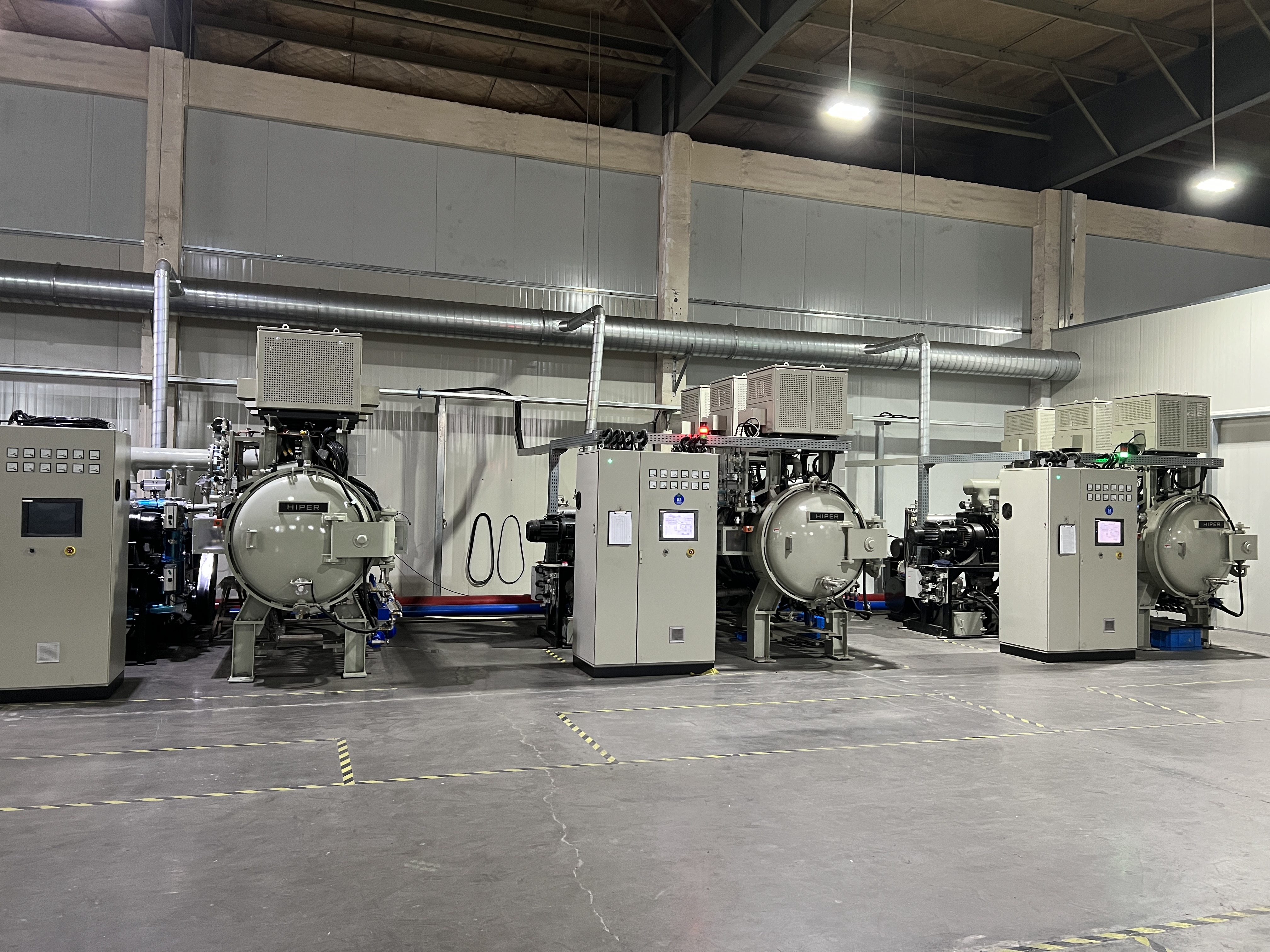
Sintering is where powder metallurgy magic happens. The green or brown part is heated in a controlled-atmosphere furnace to 70-90% of the metal's melting point. At this temperature, metal particles bond through solid-state diffusion — atoms migrate across particle boundaries, fusing them into a continuous solid without ever reaching the liquid phase.
Sintering Parameters
| Material | Sintering Temp. | Atmosphere | Time | Final Density |
|---|---|---|---|---|
| Iron / Low Alloy Steel | 1,120-1,150°C | H₂/N₂ (90/10) | 20-30 min | 85-92% TD |
| Stainless Steel (316L) | 1,280-1,350°C | Vacuum or H₂ | 60-120 min | 96-99% TD |
| Stainless Steel (17-4PH) | 1,300-1,380°C | Vacuum + Ar backfill | 60-120 min | 96-99% TD |
| Titanium (Ti-6Al-4V) | 1,250-1,350°C | High vacuum | 120-240 min | 96-99% TD |
| Copper | 800-900°C | H₂ or dissociated NH₃ | 15-30 min | 85-92% TD |
| Tungsten Carbide | 1,350-1,500°C | Vacuum or H₂ | 60-90 min | 97-99.5% TD |
TD = Theoretical Density. Press-and-sinter PM typically achieves 85-92% TD, while MIM reaches 96-99% TD because the finer powder and higher sintering temperatures allow more complete densification. This density difference directly impacts mechanical properties — MIM parts have tensile strength comparable to wrought metal, while conventional PM parts are 10-20% lower.
Sintering Shrinkage
As particles fuse and pores close, the part shrinks uniformly. MIM parts shrink 15-22% linearly (depending on powder loading), while press-and-sinter parts shrink 0.1-0.3%. This shrinkage must be precisely predicted and compensated for in the mold/die design — it is the primary source of dimensional variation in sintered parts.
Step 6: Post-Processing
Sintered parts may undergo additional operations to achieve final specifications:
- Heat treatment: Hardening, tempering, case-carburizing, or precipitation hardening (e.g., 17-4PH H900 condition) to achieve target hardness. Our clipper blades are heat-treated to HRC 60-62.
- Sizing/Coining: Re-pressing sintered parts in a precision die to tighten critical dimensions. Common in press-and-sinter PM to achieve ±0.025mm tolerances on specific features.
- Machining: Secondary CNC operations on features that require tighter tolerances than sintering can achieve — typically threads, bores, and mating surfaces.
- Surface finishing: Grinding, lapping, polishing, tumbling, bead blasting, or electroplating for cosmetic or functional requirements. Our blade lapping achieves mirror-finish cutting edges.
- Steam treatment: Exposing iron-based sintered parts to superheated steam to form a thin Fe₃O₄ layer, sealing surface porosity and improving corrosion resistance.
- Infiltration: Filling open porosity with a lower-melting-point metal (typically copper into iron) to achieve near-full density and improve mechanical properties.
Step 7: Quality Control and Inspection
Every powder metallurgy part must be verified against specifications before shipment:
- Dimensional inspection: CMM (Coordinate Measuring Machine) for critical dimensions, optical comparators for profiles, go/no-go gauges for production-line sampling
- Density measurement: Archimedes method (ASTM B962) — every sintering batch verified
- Hardness testing: Rockwell (HRC/HRB) or Vickers microhardness, per ASTM E18/E384
- Tensile testing: Destructive testing of witness samples from each sintering lot (ASTM E8)
- Metallography: Cross-section analysis to verify microstructure, porosity distribution, and sintering quality
- Surface roughness: Profilometer measurement (Ra value) for surface-critical applications
At SUMTHIN, our certifications include ISO 9001:2015, ISO 14001:2015, and SGS audit. We provide full material certifications, dimensional reports, and PPAP documentation for automotive and medical customers.
Press-and-Sinter PM vs MIM: Which Process to Choose?
| Factor | Press-and-Sinter PM | MIM |
|---|---|---|
| Part complexity | 2D shapes, limited undercuts | Full 3D complexity, internal features |
| Part weight | 10g - 5kg | 0.1g - 200g |
| Density achievable | 85-92% TD | 96-99% TD |
| Tolerance | ±0.05-0.1mm | ±0.3% (±0.03mm on 10mm) |
| Economic volume | 10,000 - 1,000,000+ | 5,000 - 500,000 |
| Tooling cost | $5,000 - $30,000 | $3,000 - $50,000 |
| Material options | Iron-based, copper, brass | Stainless steel, Ti, Fe-Ni, tool steel |